



How to retrofit Audi Side Assist, Exit Warning, Rear Cross Traffic Assist and Pre Sense rear on an Audi A4 B9: parts, rear radars, door wiring, Component Protection and coding
This guide describes how to retrofit Audi Side Assist on an Audi A4 B9 using the third-generation Bosch rear radars. The same two radars also enable Exit Warning, Rear Cross Traffic Assist and Pre Sense rear. The retrofit requires the two rear radars with their brackets, the warning LEDs in the mirrors and in the doors, door control units that support these functions, Component Protection removal with ODIS and the coding of several modules.
✅ Status: working
This retrofit has been successfully installed and tested on my Audi A4 B9, and it is still active.
Contents
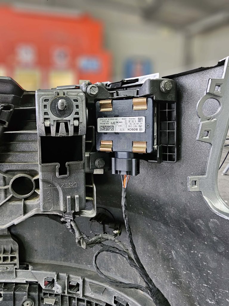
1. What this retrofit enables
| Function | Description |
|---|---|
| Side Assist | Also known as SWA (Spurwechselassistent) or BSD (blind spot detection): warns with an LED in the exterior mirror when a vehicle is in the blind spot or approaching fast from behind |
| Exit Warning | Visual warning that alerts occupants when vehicles or cyclists are approaching from behind as the doors are opened |
| Rear Cross Traffic Assist | Also known as RCTA: monitors the area behind the car while reversing and warns of vehicles and other objects approaching from the sides |
| Pre Sense rear | Warns when a rear collision is imminent; it closes windows and sunroof, activates the hazard lights and tensions the seat belts, if equipped |
2. Needed parts and price
| Group | Part number | Qty | Description |
|---|---|---|---|
| Radars | 4M0 907 566 D | 1 | Right rear radar [MASTER] |
4M0 907 590 D | 1 | Left rear radar [SLAVE] | |
8W0 907 175 | 1 | Left radar bracket [sedan] | |
8W0 907 176 | 1 | Right radar bracket [sedan] | |
| Exit Warning LEDs | 8W0 947 356 B | 2 | Front Exit Warning LED |
8W0 947 356 H | 2 | Rear Exit Warning LED | |
4B0 972 623 | 4 | Exit Warning LED connector | |
1K0 972 923 | 2 | Connector for rear door ECUs | |
| Connectors and pins | 1-968700-1 | 4 | Splitter connector |
N90764701 | 10 | Female pin connectors | |
| Door ECUs | 4M0 959 792 C | 1 | Front passenger side |
4M0 959 793 C | 1 | Front driver side | |
4M0 959 795 C | – | Rear side |
Diagnostic tools: VAS interface with ODIS online for Component Protection removal, and VCDS for coding. The total cost of the retrofit was about 800 €.
ℹ️ Sedan brackets
The bracket part numbers listed above are for the sedan. On the Avant the bumper is different: check the correct brackets for your body type before ordering.
3. How the system works
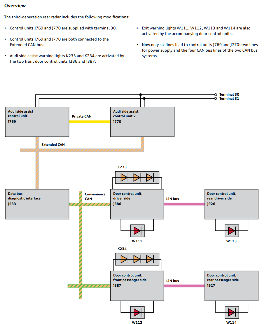
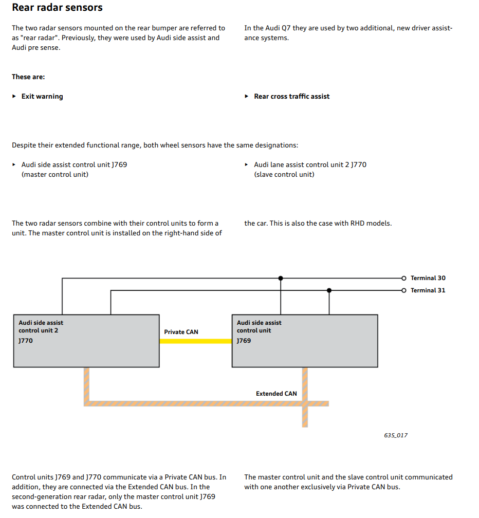
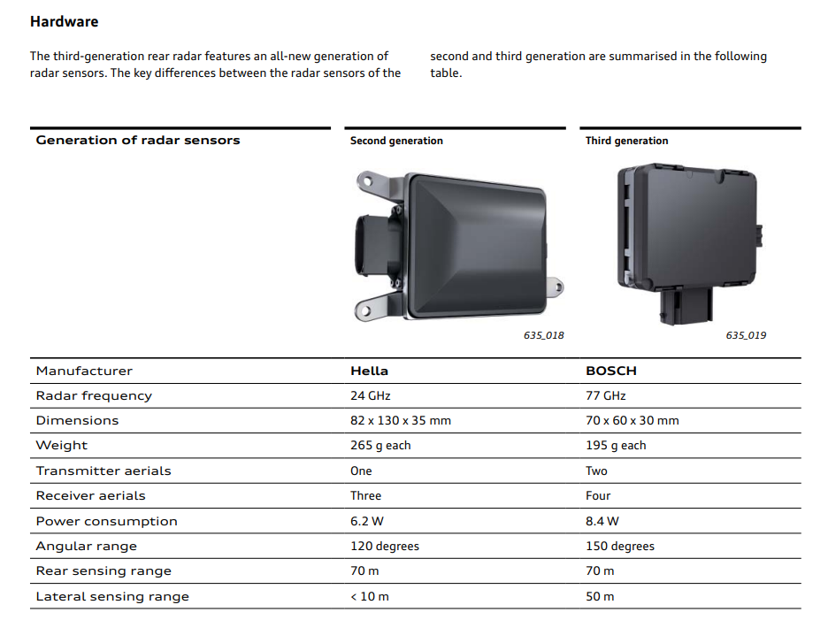
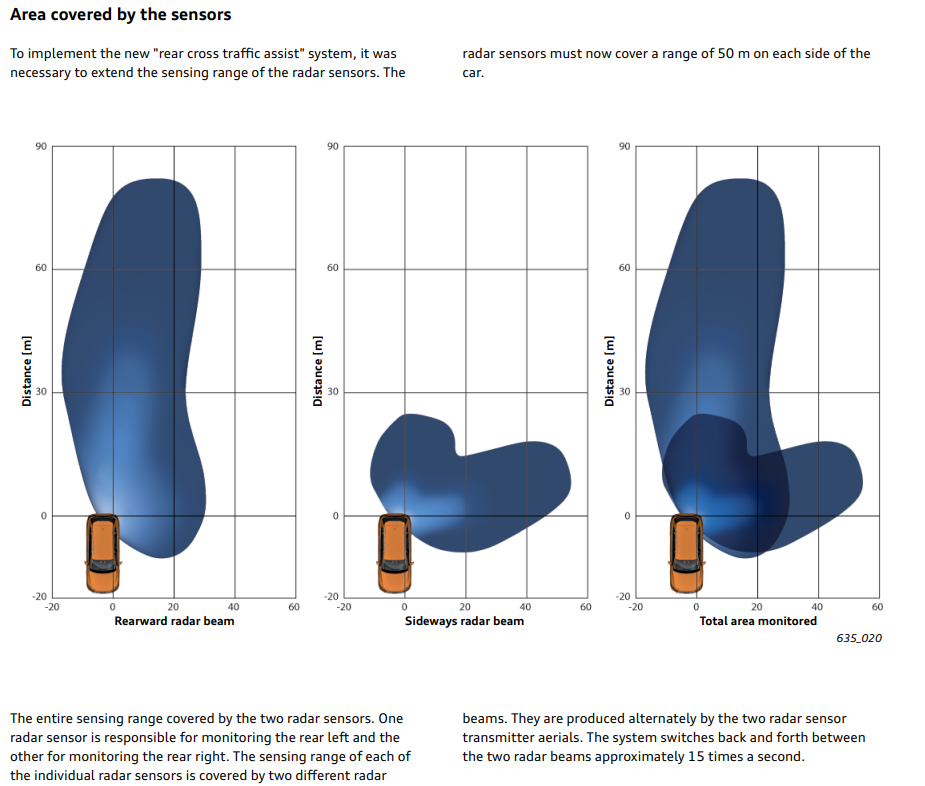
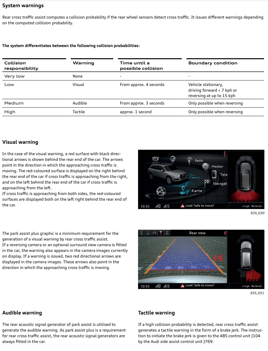
The pages below come from the Audi self-study programme on the third-generation rear radar. The two radars (J769 master and J770 slave) talk to each other over a Private CAN bus and are both connected to the Extended CAN bus. The mirror warning lamps K233 and K234 are driven by the front door control units J386 and J387, while the exit warning lamps W111–W114 are driven by the respective door control units.
4. Procedure
4.1 Mounting the radars
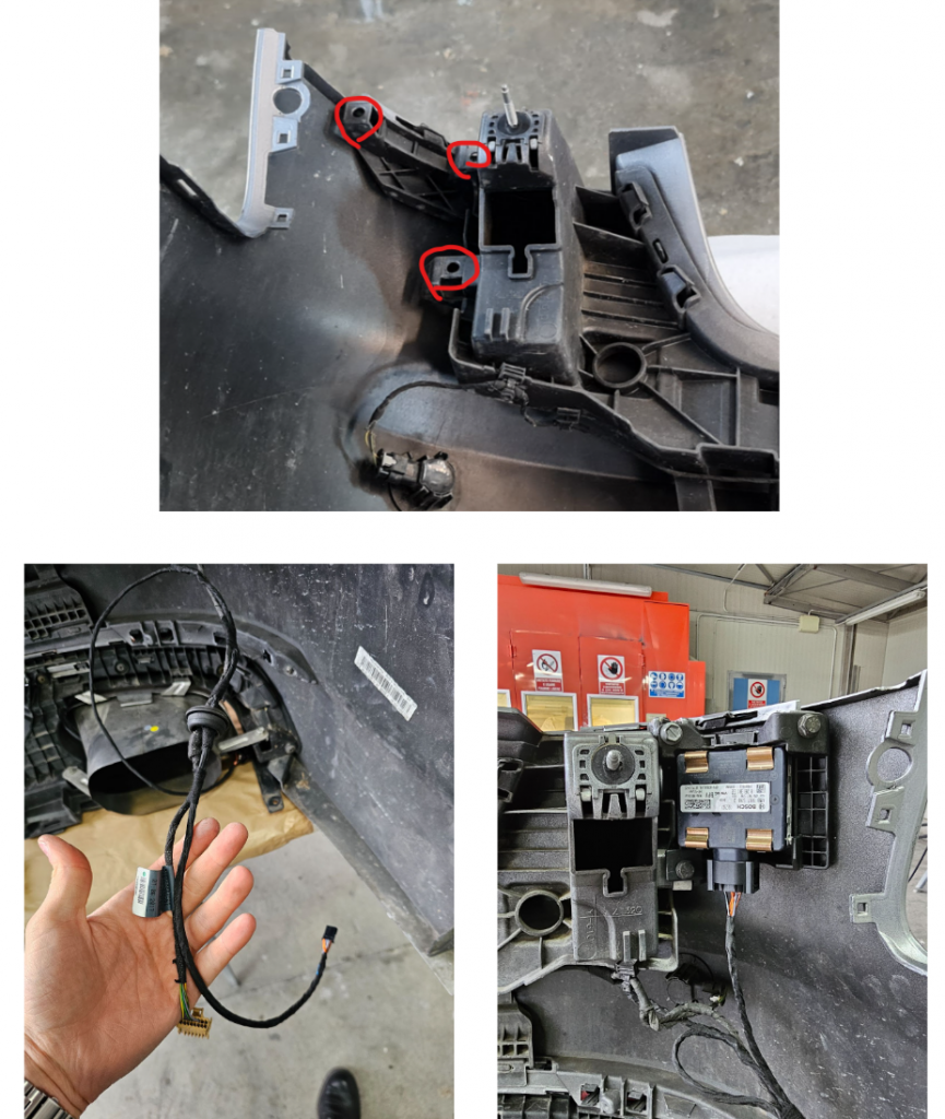
The rear bumper must be removed. Fit the brackets in the bumper at the points circled in red, then mount the radars: the master (4M0 907 566 D) on the right and the slave (4M0 907 590 D) on the left.
4.2 Wiring the radars
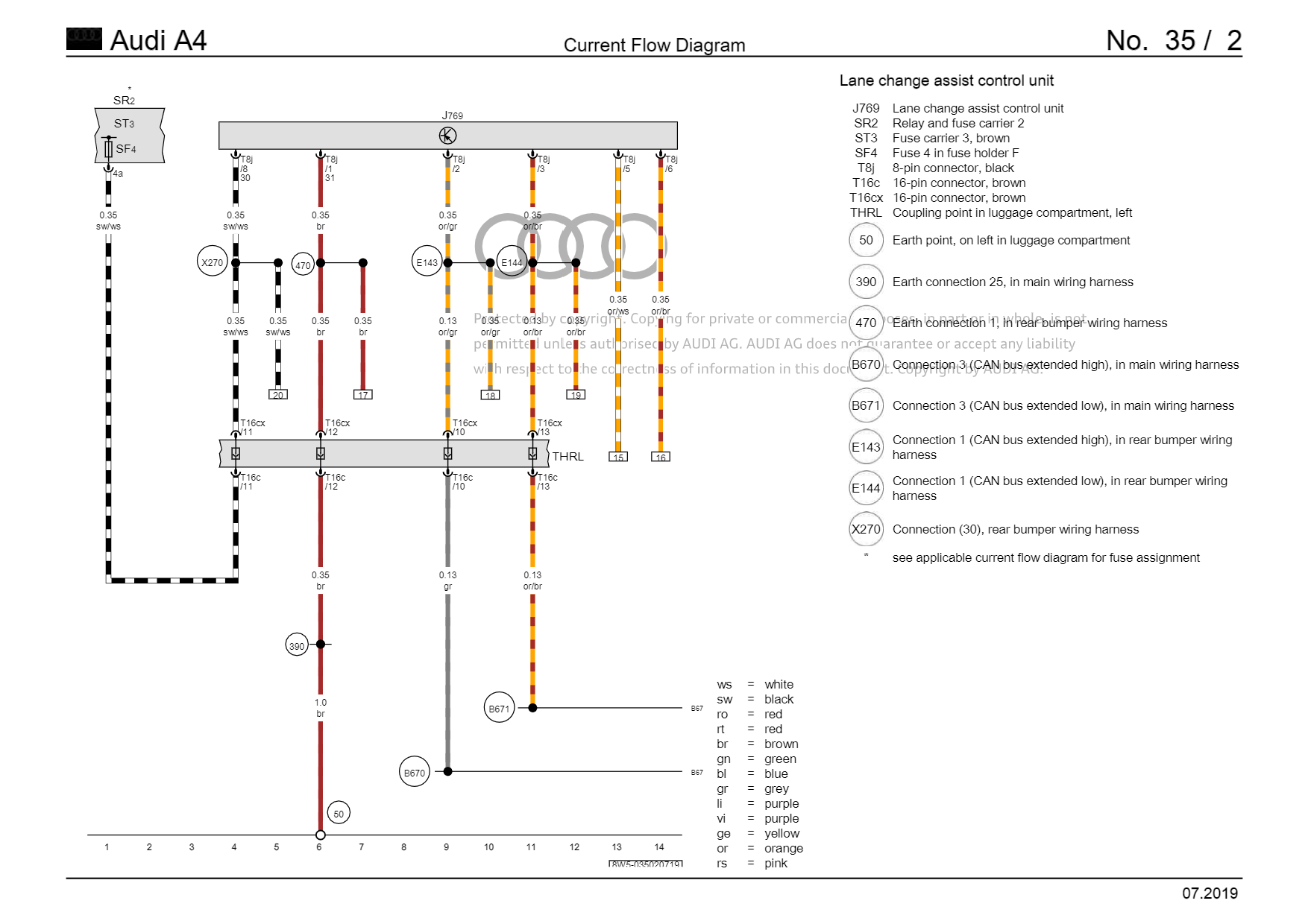
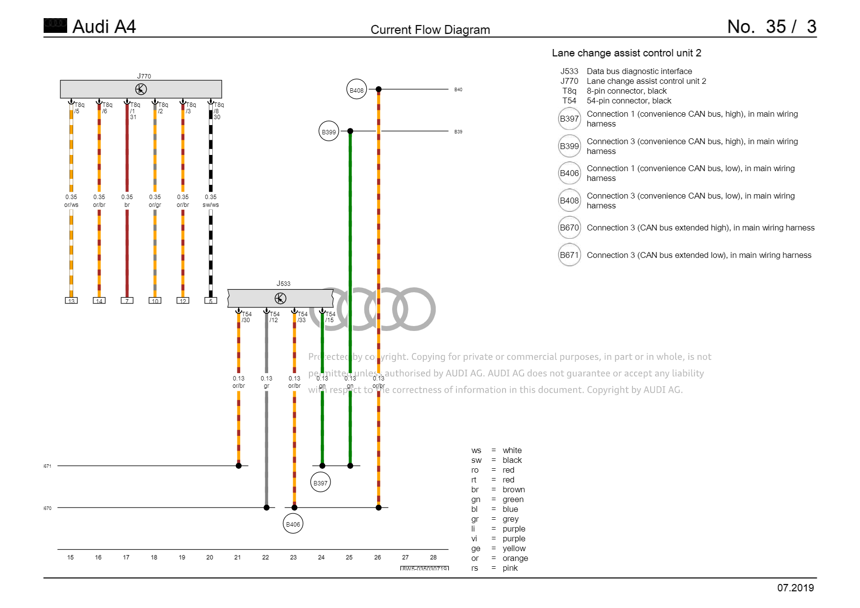
Both radars use an 8-pin connector (T8j on J769, T8q on J770) with the same pin assignment:
| Pin | Function |
|---|---|
| 1 | Terminal 31 (earth) |
| 2 | Extended CAN high |
| 3 | Extended CAN low |
| 5 – 6 | Private CAN between master and slave |
| 8 | Terminal 30 (permanent positive) |
On the A4 B9 the Extended CAN reaches the gateway J533 through the coupling point in the left side of the luggage compartment (THRL), and the master radar is powered by fuse SF4 in fuse holder ST3 of the SR2 carrier. Check the details in the wiring diagrams:
4.3 Wiring the front doors
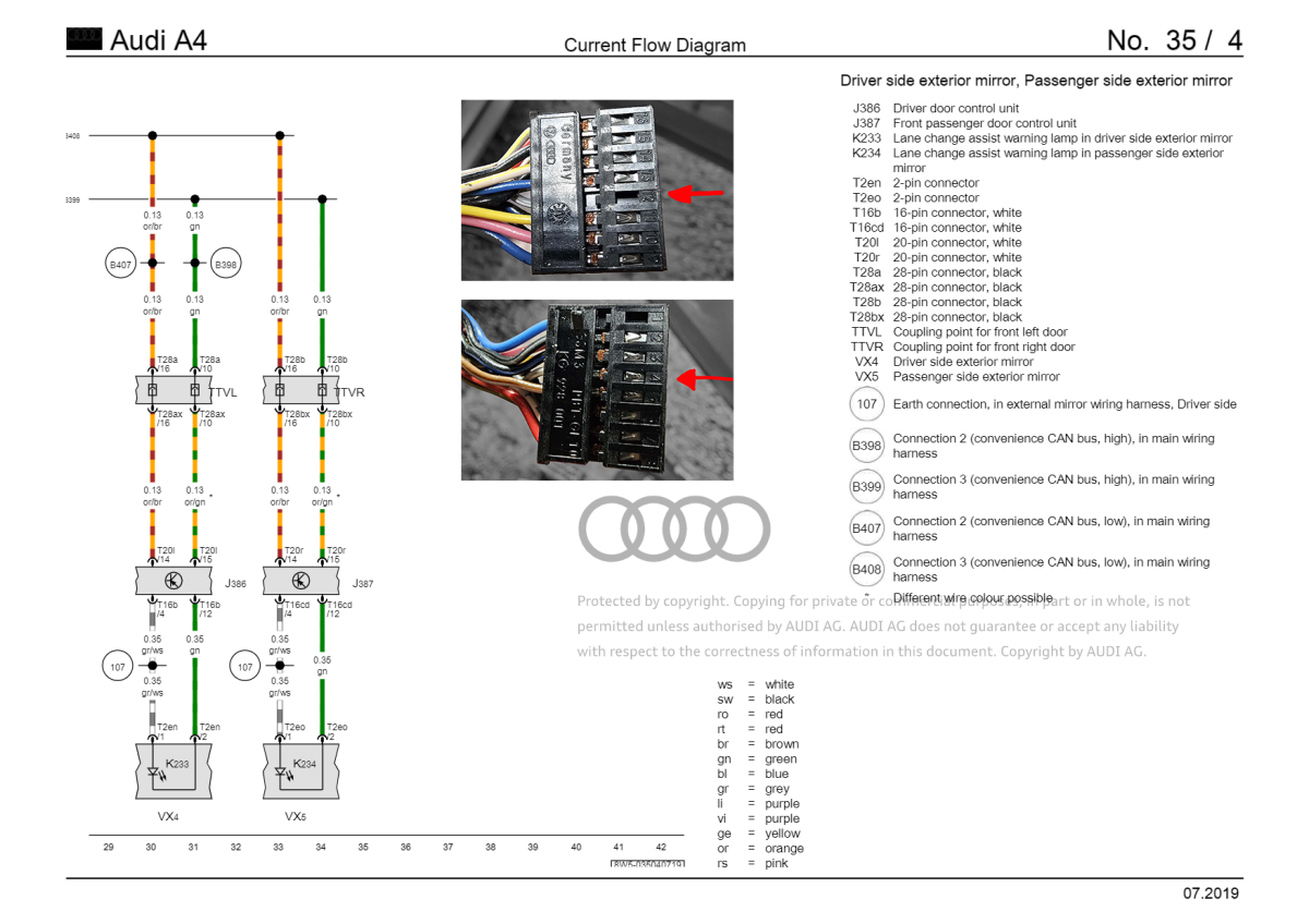
The Side Assist warning lamps in the exterior mirrors (K233 driver side, K234 passenger side) are driven by the front door control units J386 and J387. The red arrows in the photos show the pins to populate on the mirror connector:
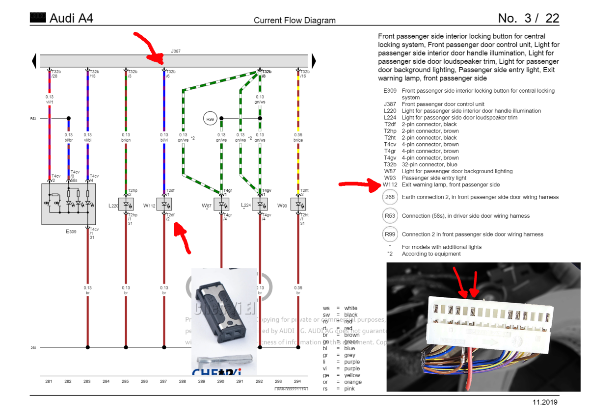
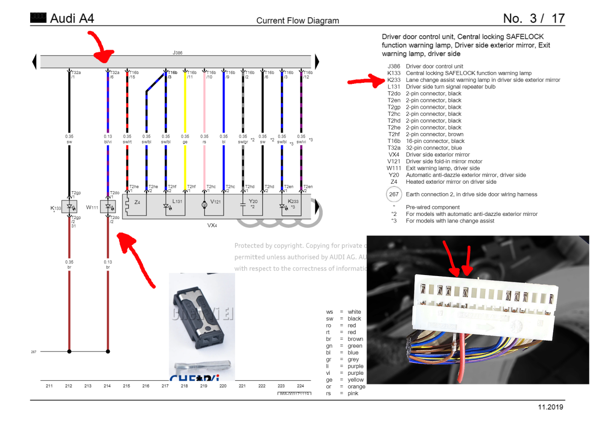
The front Exit Warning lamps (W111 driver side, W112 passenger side) are connected to the 32-pin connector of the door control unit (pin 6: T32a/6 on J386, T32b/6 on J387) and to the door earth point. Use the 4B0 972 623 connectors for the LEDs and the N90764701 pins for the door control unit connector:
4.4 Wiring the rear doors
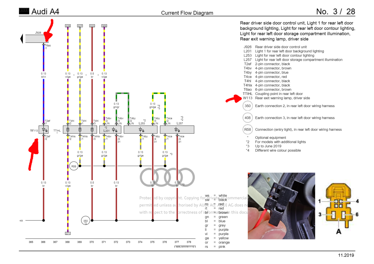
The rear Exit Warning lamps (W113 driver side, W114 passenger side) are driven by the rear door control units J926 and J927. On the driver side the lamp is connected to pin T6ao/1 of J926 and to the door earth point; use the 1K0 972 923 connector on the rear door control unit:
4.5 Component Protection removal
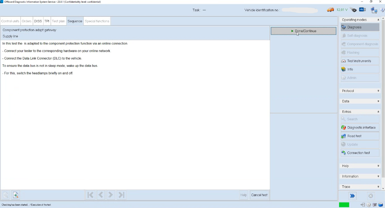
The radars and the door control units come from other cars and are protected by Component Protection: remove it with ODIS online. Start the Component protection adapt gateway sequence and follow the instructions: connect the tester to the online network and to the car, then wake up the data bus by switching the headlights briefly on and off.
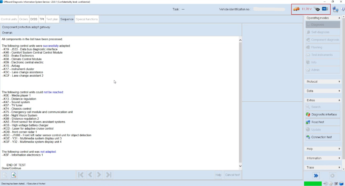
At the end ODIS lists the control units that have been adapted. Among them you must find K3C – Lane change assistance and KCF – Lane change assistant 2, i.e. the two radars:
⚠️ Keep the battery charged
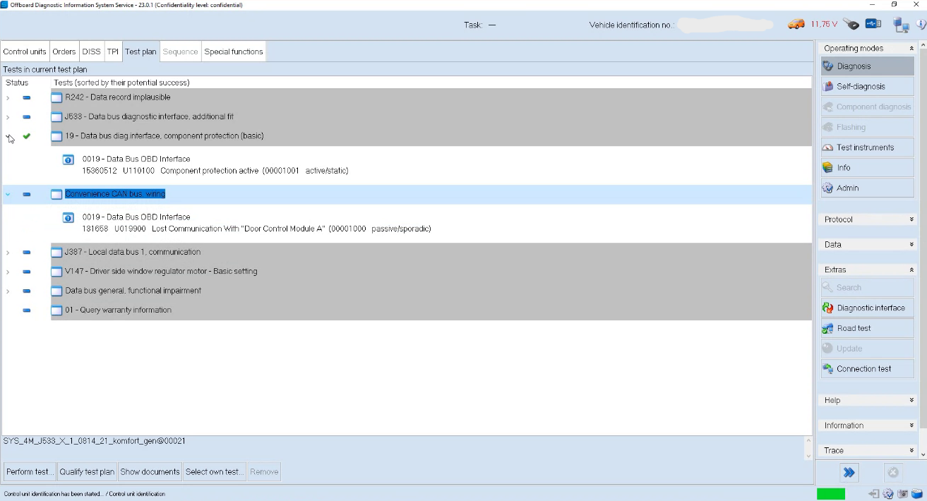
The procedure keeps the car awake for a long time with many control units active: connect a battery charger or power supply before starting. In the screenshots the voltage had already dropped below 12 V.
4.6 Coding
Code the following modules with VCDS. In the tables, "Byte X bit Y = 1" means that the bit must be enabled in the long coding.
03 ABS – Long coding
| Byte | Change | With AutoHold | Without AutoHold |
|---|---|---|---|
| 18 | bit 3 = 1 | DA [11011010] | 9A [10011010] |
| 30 | bit 4 = 1 | 5B [01011011] | 59 [01011001] |
ℹ️ ABS reference values
The hexadecimal values are those of my car. On your car, start from your own coding and only enable the bits shown in the Change column.
Other modules
| Module | Type | Change |
|---|---|---|
| 17 Instruments | Long coding | Byte 5 bit 3 = 1 [Lane change assistance] |
| A5 Front camera | Long coding | Byte 11 bit 1 = 1 [SWA] |
| 09 Central Electrics | Long coding | Byte 37 bit 0 = 1 [rtca_support_config] |
| 42 Door Elect Driver | Long coding | Byte 11 bit 4 = 1 [SWA] Byte 11 bit 5 = 1 [Exit Warning] |
| 52 Door Elect Pass | Long coding | Byte 11 bit 4 = 1 [SWA] Byte 11 bit 5 = 1 [Exit Warning] |
| BB – BC Rear doors | Long coding | Byte 11 bit 4 = 1 [SWA] Byte 11 bit 5 = 1 [Exit Warning] |
5F Information Electronics – Adaptation
| Channel | Value |
|---|---|
SWA_0x1A | activated |
SWA_0x1A_msg_bus | Terminal 15 |
[LO]_menu_display_lane_assistant | activated |
[LO]_menu_display_lane_assistant_over_threshold_high | activated |
5. Notes: aftermarket mirror LEDs
I first bought an aftermarket Audi Side Assist kit from AliExpress, and the Side Assist LEDs in the mirrors did not work. The driver door control unit (42) reported this fault:
⚠️ 196885 – Function Lighting for Lane Change Assistant LED Display
B1789 01 [009] – Electrical Failure
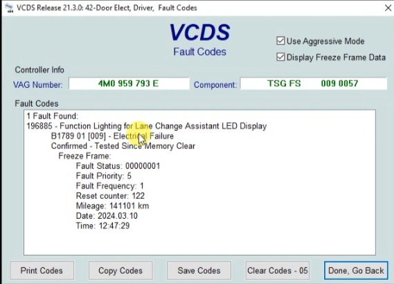
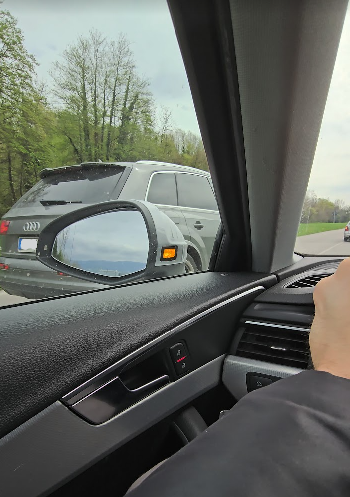
After some troubleshooting and advice, it turned out that the problem was the aftermarket LEDs. I bought a pair of original ones (100 € for left and right!) and now everything works perfectly.
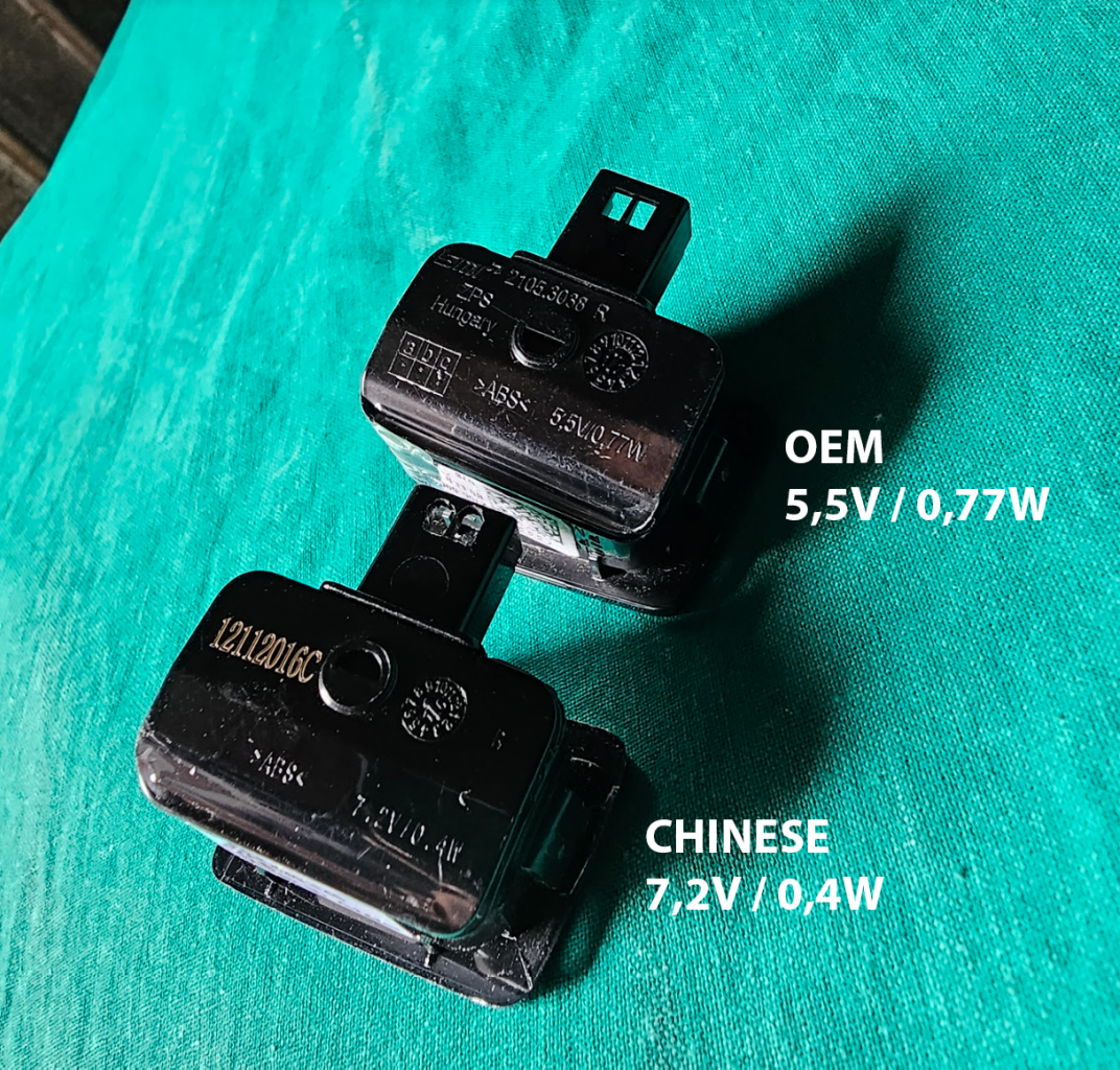
Note the differences between the Chinese LED and the original one: the OEM part is rated 5.5 V / 0.77 W, the Chinese one 7.2 V / 0.4 W.
💡 Buy original mirror LEDs
If you get fault B1789 on the door modules after the retrofit, check the wiring first, then the mirror LEDs: the electrical ratings of the aftermarket parts do not match what the door control unit expects.
6. Summary
| Step | What to do |
|---|---|
| Radars | Remove the rear bumper, fit brackets and radars: master on the right, slave on the left (section 4.1) |
| Radar wiring | Terminal 30/31, Extended CAN to J533, Private CAN between radars (section 4.2) |
| Front doors | Mirror LEDs K233/K234 and Exit Warning lamps W111/W112 (section 4.3) |
| Rear doors | Exit Warning lamps W113/W114 on J926/J927 (section 4.4) |
| Component Protection | ODIS online: check that K3C and KCF are adapted (section 4.5) |
| Coding | 03, 17, 5F, A5, 09, 42, 52, BB/BC (section 4.6) |
| Fault B1789 on mirror LED | Replace aftermarket LEDs with original ones (section 5) |


Scrivi un commento